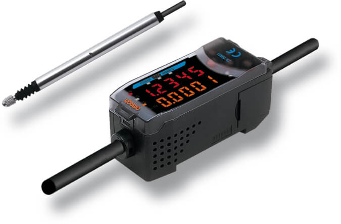
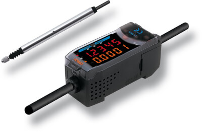
Connexion

Nous rencontrons des problèmes techniques. Votre demande ne peut être traitée. Veuillez nous excuser et ré-essayer plus tard. Détails :

Download

Inscription

Nous rencontrons des problèmes techniques. Votre demande ne peut être traitée. Veuillez nous excuser et ré-essayer plus tard. Détails :

Download

Merci pour votre inscription à Omron

Un e-mail qui vous permettra de terminer la création de votre compte a été envoyé à

Revenir au site Web

obtenir un accès direct

Veuillez remplir le formulaire ci-dessous pour accéder directement au contenu de cette page.

Text error notification

Text error notification

Checkbox error notification

Checkbox error notification

Nous rencontrons des problèmes techniques. Votre demande ne peut être traitée. Veuillez nous excuser et ré-essayer plus tard. Détails :

Download

Nous vous remercions de votre intérêt.

Vous avez désormais accès à ZX-T

Un email de confirmation a été envoyé à

Continuer vers la page

Veuillez vous ou obtenir un accès direct pour télécharger ce document.

ZX-T

ZX-T

Capteur palpeur intelligent

Le ZX-T est idéal pour les applications où l'objet cible peut contenir des dépôts d'huile ou d'autres microstructures. Dans ce cas, la mesure par contact est la méthode la plus fiable.

  • Concept de plateforme modulaire pour les différentes technologies de détection
  • Types à rétention d'air pour une inspection automatisée
  • Mesure multipoints avec jusqu'à 8 capteurs
  • Alarme force de pression pour éviter les dysfonctionnements
  • Roulement à billes renforcé pour une longue durée de vie

Caractéristiques et références

Ordering information

Sensors

Sensor heads

Size

Type

Sensing distance

Resolution (See note.)

Order code

6 dia.

Short type

1 mm

0.1 µm

ZX-TDS01T

Standard type

4 mm

ZX-TDS04T

Low-load type

ZX-TDS04T-L

8 dia.

Standard type

10 mm

0.4 µm

ZX-TDS10T

Ultra-low-load type

ZX-TDS10T-L

Air lift type

ZX-TDS10T-V

Air lift/air push type

ZX-TDS10T-VL

Note: The resolution refers to the minimum value that can be read when a ZX-TDA_1 amplifier unit is connected.

Amplifier units

Power supply

Output type

Order code

DC

NPN

ZX-TDA11

PNP

ZX-TDA41

Accessories (order separately)

Calculating unit


Order code

Calculating unit

ZX-CAL2

ZX-series communications interface unit

Name

Order code

ZX-series communications interface unit

ZX-SF11


SmartMonitor sensor setup tool for Personal Computer connection

Name

Order code

ZX-series communications interface unit

ZX-SF11

ZX-series communications interface unit

+ setup software (CD-ROM)

ZX-SFW11EV31 , 2

ZX-series sensor setup and logging software (CD-ROM)

ZX-SW11EV31

Cables with connectors on both ends (for extension)*

Cable length

Order code

1 m

ZX-XC1A

4 m

ZX-XC4A

8 m

ZX-XC8A

* Robot cable models are also available. The model numbers are ZX-XC_R.

Preamplifier mounting brackets
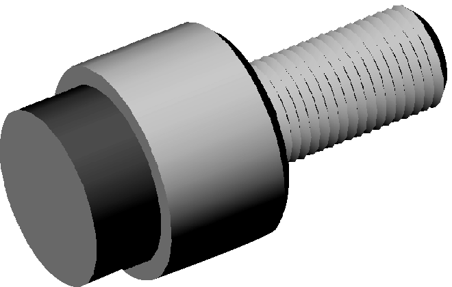
Remarks

Order code

Attached to each sensor head

ZX-XBT1

For DIN track mounting

ZX-XBT2

Actuators

Type (material)

Screw section

Appearance

Application

Applicable sensor
(see note.)

Order code

ZX-TDS_T


Ball type (steel)

Female screw

M2.5x0.45


Measuring ordinary flat surfaces (standard
actuator supplied with the ZX-TDS series)


D5SN-TB1

Ball type
(carbide steel)

Female screw

M2.5x0.45


Measurements where abrasion resistance
is critical

Measured objects: Carbide (HR90) or lower.


D5SN-TB2

Ball type (ruby)

Female screw

M2.5x0.45


Measurements where abrasion resistance
is critical

Measured objects: Carbide (HR90) or higher.


D5SN-TB3

Needle type
(carbide steel)

Male screw

M2.5x0.45


Measuring the bottom of grooves and holes


D5SN-TN1

Flat
(carbide steel)

Male screw

M2.5x0.45


Measuring spherical objects


D5SN-TF1

Conversion adapter
(stainless steel)

Through-hole female screw

M2.5x0.45


Mounting D5SN-TN1/-TF1 or commercially
available actuators on ZX-TDS-series sensors


D5SN-TA

Note: Replacement possible Conversion adapter required

Specifications

Amplifier units

Item

ZX-TDA11

ZX-TDA41

Measurement period

1 ms

Possible average count settings3

1, 16, 32, 64, 128, 256, 512, or 1,024

Linear output4

Current output: 4 to 20 mA/F.S., max. load resistance: 300 Ω

Voltage output: ±4 V (±5 V, 1 to 5 V5), output impedance: 100 Ω

Judgement outputs
(3 outputs: HIGH/PASS/LOW)

NPN open-collector outputs, 30 VDC, 30 mA max.
Residual voltage: 1.2 V max.

PNP open-collector outputs, 30 VDC, 30 mA max.
Residual voltage: 2 V max.

Zero reset input, timing input, reset input, judgement output hold input

ON: Short-circuited with 0-V terminal or 1.5 V or less

OFF: Open (leakage current: 0.1 mA max.)

ON: Supply voltage short-circuited or supply voltage of 1.5 V or less

OFF: Open (leakage current: 0.1 mA max.)

Function

  • Measurement value display
  • present value/set value/output value display
  • Display reverse
  • ECO mode
  • number of display digit changes
  • Sample hold
  • peak hold
  • bottom hold, peak-to-peak hold
  • Self-peak hold
  • self-bottom hold
  • zero reset
  • Initial reset
  • direct threshold value setting
  • position teaching
  • Hysteresis width setting
  • timing inputs
  • reset input
  • Judgement output hold input
  • monitor focus
  • (A-B) calculations6
  • (A+B) calculations (see note 4.)
  • sensor disconnection detection
  • Zero reset memory
  • function lock
  • non-measurement setting
  • Clamp value setting
  • scale inversion
  • zero reset indicator
  • Span adjustment
  • warming-up display
  • pressing force alarm

Indicators

Judgement indicators: High (orange), pass (green), low (yellow), 7-segment main digital display (red), 7-segment sub-digital
display (yellow), power ON (green), zero reset (green), enable (green)

Power supply voltage

12 to 24 VDC±10%, ripple (p-p): 10% max.

Current consumption

140 mA max. (with sensor connected), for 24-VDC power supply voltage: 140 mA max. (with sensor connected)

Ambient temperature

Operating and storage: 0 to 50°C (with no icing or condensation)

Temperature characteristic

0.03% F.S./°C

Connection method

Prewired (standard cable length: 2 m)

Weight (packed state)

Approx. 350 g

Materials

Case: PBT (polybutylene terephthalate), cover: Polycarbonate

Sensor heads

Item

ZX-TDS01T

ZX-TDS04T

ZX-TDS04T-L

Measurement range

1 mm

4 mm

Maximum actuator travel distance

Approx. 1.5 mm

Approx. 5 mm

Resolution7

0.1 µm

Linearity8

±0.3% F.S.

Operating force 9

Approx. 0.7 N

Approx. 0.25 N

Degree of protection (sensor head)

IEC60529, IP67

IEC60529, IP54

Mechanical durability

10,000,000 operations min.

Ambient temperature

Operating: 0 to 50°C, storage: - 15 to 60°C (with no icing or condensation)

Ambient humidity

Operating and storage: 35% to 85% (with no icing or condensation)

Temperature characteristic10

Sensor head

0.03% F.S./°C

Preamplifier

0.01% F.S./°C

Weight (packed state)

Approx. 100 g

Materials

Sensor head

Stainless steel

Preamplifier

Polycarbonate

Accessories

Instruction manual, preamplifier mounting brackets (ZX-XBT1)


1. When using the ZX-TDA11/41 with the SmartMonitor, either the ZX-SFW11EV3 or the
ZX-SW11EV3 SmartMonitor must be used. Earlier versions cannot be used.

2. The ZX-SFW11EV3 SmartMonitor can be used only to set functions and monitor waveforms.

3. The response speed of the linear output is calculated as the measurement period x (average count setting + 1).
The response speed of the judgement outputs is calculated as the measurement period x (average count setting + 1).

4. The output can be switched between a current output and voltage output using a switch on the bottom of the amplifier unit.

5. Setting is possible via the monitor focus function.

6. A calculating unit (ZX-CAL2) is required.

7. The resolution is given as the minimum value that can be read when a ZX-TDA_1 amplifier unit is connected. This value is taken 15 minutes after turning ON the power with the average number of operations set to 256.

8. The linearity is given as the error in an ideal straight line displacement output.

9. These figures are representative values that apply for the measurement mid-point, and are for when the provided actuator is used, with the actuator moving downwards. If the actuator moves horizontally or upwards, the operating force will be reduced. Also, if an actuator other than the standard one is used, the operating force will vary with the weight of the actuator itself.

10. These figures are representative values that apply for the mid-point of the measurement range.

En quoi pouvons-nous vous aider ?

Pour toute question ou demande de devis, veuillez nous contacter ou envoyer une demande.

0825 825 679
Contactez-nous

Contactez-moi ZX-T

zx-t img prod

Merci de compléter tous les champs *. Les informations sont traitées de manière confidentielle.

Text error notification

Text error notification

Text error notification

Text error notification

Text error notification

Country error notification

Text area error notification

Checkbox error notification

Checkbox error notification

Merci de votre demande. Nous reviendrons vers vous dès que possible.

Nous rencontrons des problèmes techniques. Votre demande ne peut être traitée. Veuillez nous excuser et ré-essayer plus tard. Détails :

Download
0825 825 679
0825 825 679
Demander un devis
Demander un devis

Devis pour ZX-T

Vous pouvez utiliser ce formulaire pour demander un devis sur le produit de votre choix. Merci de compléter tous les champs *. Les informations sont traitées de manière confidentielle.

zx-t img prod

Détails personnels

ZX-T

Text error notification

Text error notification

Text error notification

Text error notification

Country error notification

Détails du devis

Select notification error

Select notification error

Text area error notification

Checkbox error notification

Checkbox error notification

Merci de votre demande. Nous vous enverrons l'information demandée au plus tôt.

Nous rencontrons des problèmes techniques. Votre demande ne peut être traitée. Veuillez nous excuser et ré-essayer plus tard. Détails :

Download
Demander un devis
Demander un devis

Téléchargements