Connexion

Nous rencontrons des problèmes techniques. Votre demande ne peut être traitée. Veuillez nous excuser et ré-essayer plus tard. Détails :

Download

Inscription

Nous rencontrons des problèmes techniques. Votre demande ne peut être traitée. Veuillez nous excuser et ré-essayer plus tard. Détails :

Download

Merci pour votre inscription à Omron

Un e-mail qui vous permettra de terminer la création de votre compte a été envoyé à

Revenir au site Web

obtenir un accès direct

Veuillez remplir le formulaire ci-dessous pour accéder directement au contenu de cette page.

Text error notification

Text error notification

Checkbox error notification

Checkbox error notification

Nous rencontrons des problèmes techniques. Votre demande ne peut être traitée. Veuillez nous excuser et ré-essayer plus tard. Détails :

Download

Nous vous remercions de votre intérêt.

Vous avez désormais accès à ZS-HL

Un email de confirmation a été envoyé à

Continuer vers la page

Veuillez vous ou obtenir un accès direct pour télécharger ce document.

ZS-HL

ZS-HL

Le capteur de mesure laser haute précision et évolutif

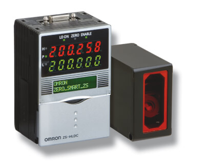
Le capteur intelligent ZS-HL offre une formidable plage de détection dynamique adaptée à toutes les surfaces (du caoutchouc au verre et aux surfaces réfléchissantes), il suffit de l'adapter à vos besoins. Le ZS-HL est la variante améliorée du ZS-L, adaptée à des distances de mesure supérieures et compatible avec les têtes de capteur et les accessoires.

  • Résolution et plage de détection dynamique optimales pour toutes les surfaces
  • Concept de plate-forme modulaire et évolutive pouvant accueillir jusqu'à 9 capteurs
  • Utilisation, installation et maintenance faciles, à la portée de n'importe quel utilisateur
  • Temps de réponse rapide de 110 µs
  • Fonction multitâche - permet de gérer jusqu'à 4 outils de mesure sur un seul contrôleur

Caractéristiques et références

Ordering information

Sensors

ZS-HL-series sensor heads

Optical system

Sensing distance

Beam shape

Beam diameter

Resolution1

Order code

Regular reflective models

20±1 mm

Line beam

1.0 mm × 20 µm

0.25 µm

ZS-HLDS2T

25±2 mm

2.2 mm × 45 µm

0.6 µm

ZS-HLDS2VT

Diffuse reflective models

50±5 mm

1.0 mm × 30 µm

0.25 µm

ZS-HLDS5T

100±20 mm

3.5 mm × 60 µm

1 µm

ZS-HLDS10

600±350 mm

16 mm × 0.3 mm

8 µm

ZS-HLDS60

1500±500 mm

40 mm × 1.5 mm

500 µm

ZS-HLDS150

ZS-HL-series sensor heads (for nozzle gaps) also compatible with ZS-L controller

Optical system

Sensing distance

Beam shape

Beam diameter

Resolution2

Order code

Regular reflective models

10±0.5 mm

Line beam

900x25 µm

0.25 µm

ZS-LD10GT

15±0.75 mm

ZS-LD15GT

ZS-L-series sensor heads

Optical system

Sensing distance

Beam shape

Beam diameter

Resolution3

Order code

Regular reflective models

20±1 mm

Line beam

900 × 25 µm

0.25 µm

ZS-LD20T

Spot beam

25 µm dia.

ZS-LD20ST

40±2.5 mm

Line beam

2000 × 35 µm

ZS-LD40T

Diffuse reflective models

50±5 mm

Line beam

900 × 60 µm

0.8 µm

ZS-LD50

Spot beam

50 µm dia.

ZS-LD50S

80±15 mm

Line beam

900 × 60 µm

2 µm

ZS-LD80

130±15 mm

Line beam

600 × 70 µm

3 µm

ZS-LD130

200 ±50 mm

Line beam

900 × 100 µm

5 µm

ZS-LD200

350 ±135 mm

Spot beam

240 µm dia.

20 µm

ZS-LD350S

ZS-HL-series sensor controllers

Supply voltage

Control outputs

Order code

24 VDC

NPN outputs

ZS-HLDC11

PNP outputs

ZS-HLDC41

ZS-HLDC41A
(incl. USB cable + Smart monitor)

Multi-controllers

Supply voltage

Control outputs

Order code

24 VDC

NPN outputs

ZS-MDC11

PNP outputs

ZS-MDC41

Data storage units

Supply voltage

Control outputs

Order code

24 VDC

NPN outputs

ZS-DSU11

PNP outputs

ZS-DSU41

Accessories (sold separately)

Controller link

Item

Order code

Controller link

ZS-XCN

Panel mount adapter

Model

Order code

For 1st controller

ZS-XPM1

For expansion (from 2nd controller on)

ZS-XPM2

Cables for connecting to a Personal Computer

Type

Quantity

Order code

RS-232C

1

ZS-XRS2

USB

1

ZS-XUSB2

Extension cables for sensor heads

Cable length

Quantity

Order code

1 m

1

ZS-XC1A

4 m

1

ZS-XC4A

5 m

1

ZS-XC5B4 , 5

8 m

1

ZS-XC8A

10 m

1

ZS-XC10B1

Logging software

Item

Order code

Smart monitor zero professional

ZS-SW11E

Memory card

Model

Order code

64 MB

F160-N64S(S)

128 MB

QM300-N128S

256 MB

F160-N256S

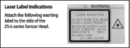
Safety precautions for using laser equipment

Specifications

Sensor heads

ZS-HL-series sensor heads

Item

ZS-HLDS2T

ZS-HLDS2VT

ZS-HLDS5T

ZS-HLDS10

ZS-HLDS60

ZS-HLDS150

Applicable controllers

ZS-HLDC series

Optical system

Regular
reflection

Diffuse reflection

Regular
reflection

Regular
reflection

Diffuse reflection

Regular
reflection

Diffuse reflection

Diffuse reflection

Diffuse reflection

Measuring center distance

20 mm

5.2 mm

25 mm

44 mm

50 mm

94 mm

100 mm

600 mm

1,500 mm

Measuring range

±1 mm

±1 mm

±2 mm

±4 mm

±5 mm

±16 mm

±20 mm

±350 mm

±500 mm

Light source

Visible semiconductor laser (wavelength: 650 nm, 1 mW max., JIS Clas

Visible semiconductor laser (wavelength 658 nm, 1 mW max., Class 2)

Beam shape

Line beam

Beam diameter1

1.0 mmx20 µm

2.2 mmx45 µm

1.0 mmx30 µm

3.5 mmx60 µm

0.3 mmx16 mm

1.5 mmx40 mm

Linearity2

±0.05% F.S.

±0.2 %F.S.

±0.1% F.S.

±0.07 %F.S.

(250 mm to 750 mm)

±0.1% F.S.

(750 mm to 950 mm)

±0.2 %F.S.

Resolution3

0.25 µm
(No. of samples to average: 256)

0.5 µm
(No. of samples to average: 128)

0.25 µm
(No. of samples to average: 512)

1 µm
(No. of samples to average: 64)

8 µm

(average 64)

(at 250 mm)

40 µm

(average 64)

(at 600 mm)

500 µm

(average 64)

Temperature characteristic4

0.01% F.S./°C

0.1% F.S./°C

0.01% F.S./°C

Sampling cycle

110 µs (high-speed mode), 500 µs (standard mode), 2.2 ms (high-precision mode), 4.4 ms (high-sensitivity mode)

Indicators

NEAR indicator

Lits near the measurement center, and nearer than the measurement center distance inside the measuring range.
Flashes when the measurement target is outside of the measuring range or when the received light amount is insufficient.

FAR indicator

Lits near the measurement center, and further than the measurement center distance inside the measuring range.
Flashes when the measurement target is outside of the measuring range or when the received light amount is insufficient.

Operating ambient illumination

Illumination on received light surface 3,000 lx or less (incandescent light)

Illumination on received light surface 1,000 lx or less (incandescent light)

Illumination on received light surface 500 lx or less (incandescent light)

Ambient temperature

Operating: 0 to 50°C, storage: -15 to 60°C (with no icing or condensation)

Ambient humidity

Operating and storage: 35% to 85% (with no condensation)

Degree of protection

IP64

IP67

Cable length 0.5 m: IP66, cable length 2 m: IP67

IP66 (IEC60529)

Vibration resistance (destructive)

10 to 150 Hz, 0.7 mm double amplitude, 80 min each in X, Y, and Z directions

Shock resistance (destructive)

150 m/s² 3 times each in six directions (up/down, left/right, forward/backward)

Materials

Case: aluminum die-cast, front cover: glass

Cable length

0.5 m, 2 m

2 m

0.5 m, 2 m

Weight

Approx. 350 g

Approx. 600 g

Approx. 800 g

*1 Defined as 1/e² (13.5%) of the center optical intensity in the measurement center distance. The beam diameter is sometimes influenced by the ambient conditions of the workpiece such as leaked light from the main beam.

*2 This is the error on the measured value with respect to an ideal straight line. Linear curve may change according to the workpiece. The following lists the workpieces

Model

Diffusive reflection

Mirror reflection

ZS-HLDS2T

SUS block

Glass

ZS-HLDS5T/HLDS10

White alumina ceramic

Glass

ZS-HLDS60/HLDS150

White alumina ceramic

-

ZS-HLDS2VT

-

Glass

*3 This is the “peak-to-peak” displacement conversion value of the displacement output in the measurement center distance when high-resolution mode and the average number in the table are set (For ZS-HLDS60, the maximum resolution at 250 mm is also included). The following lists the workpieces.

Model

Diffusive reflection

Mirror reflection

ZS-HLDS2T

SUS block

Glass

ZS-HLDS5T

White alumina ceramic

Glass

ZS-HLDS10

White alumina ceramic

ZS-HLDS60/HLDS150

White alumina ceramic

-

ZS-HLDS2VT

-

Glass

*4 Value obtained when the sensor part and object part are fixed with an aluminum jig.

ZS-L-series sensor heads

Item

ZS-LD20T

ZS-LD20ST

ZS-LD40T

ZS-LD10GT

ZS-LD15GT

Applicable controllers

ZS-HLDC/LDC series

Optical system

Regular reflection

Diffuse reflection

Regular reflection

Diffuse reflection

Regular reflection

Diffuse reflection

Regular reflection

Measuring center distance

20 mm

6.3 mm

20 mm

6.3 mm

40 mm

30 mm

10 mm

15 mm

Measuring range

±1 mm

±1 mm

±1 mm

±1 mm

±2.5 mm

±2 mm

±0.5 mm

±0.75 mm

Light source

Visible semiconductor laser (wavelength: 650 nm, 1 mW max., JIS Class 2)

Beam shape

Line beam

Spot beam

Line beam

Beam diameter6

900 x 25 µm

25 µm dia.

2,000 x 35 µm

Approx. 25 x 900 µm

Linearity7

±0.1%F.S

Resolution8

0.25 µm

0.25 µm

0.4 µm

0.25 µm

0.25 µm

Temperature characteristic9

0.04% FS/°C

0.04% FS/°C

0.02% FS/°C

0.04% FS/°C

Sampling cycle10

110 µs (high-speed mode), 500 µs (standard mode), 2.2 ms (high-precision mode), 4.4 ms (high-sensitivity mode)

Indicators

NEAR
indicator

Lights near the measuring center distance, and nearer than the measuring center distance inside the measuring range.

Flashes when the measurement target is outside of the measuring range or when the received light amount is insufficient.

FAR
indicator

Lights near the measuring center distance, and further than the measuring center distance inside the measuring range.

Flashes when the measurement target is outside of the measuring range or when the received light amount is insufficient.

Operating ambient illumination

Illumination on received light surface: 3,000 lx or less (incandescent light)

Ambient temperature

Operating: 0 to 50°C, storage: -15 to 60°C (with no icing or condensation)

Ambient humidity

Operating and storage: 35% to 85% (with no condensation)

Degree of protection

Cable length 0.5 m: IP66, cable length 2 m: IP67

IP40

Materials

Case: Aluminum die-cast, front cover: Glass

Cable length

0.5 m, 2 m

Weight

Approx. 350 g

Approx. 400 g

Accessories

Laser labels (1 each for JIS/EN, 3 for FDA), ferrite cores (2), insure Locks (2), instruction sheet

Laser safety labels (1 each for JIS/EN),ferrite cores (2), insure locks (2)

ZS-L-series sensor heads

Item

ZS-LD50

ZS-LD50S

ZS-LD80

ZS-LD130

ZS-LD200

ZS-LD350S

Applicable controllers

ZS-HLDC/LDC series

Optical system (reflection)

Diffuse

Regular

Diffuse

Regular

Diffuse

Regular

Diffuse

Regular

Diffuse

Regular

Diffuse

Measuring center distance

50 mm

47 mm

50 mm

47 mm

80 mm

78 mm

130 mm

130 mm

200 mm

200 mm

350 mm

Measuring range

±5 mm

±4 mm

±5 mm

±4 mm

±15 mm

±14 mm

±15 mm

±12 mm

±50 mm

±48 mm

±135 mm

Light source

Visible semiconductor laser (wavelength: 650 nm, 1 mW max., JIS Class 2)

Beam shape

Line beam

Spot beam

Line beam

Line beam

Line beam

Spot beam

Beam diameter11

900 x 60 µm

50 µm dia.

900 x 60 µm

600 x 70 µm

900 x 100 µm

240 µm dia.

Linearity12

±0.1%F.S.

±0.25%F.S.

±0.1%F.S.

±0.25%F.S.

±0.04%F.S.

Resolution13

0.8 µm

0.8 µm

2 µm

3 µm

5 µm

20 µm

Temperature characteristic14

0.02% FS/°C

0.02% FS/°C

0.01% FS/°C

0.02% FS/°C

0.02% FS/°C

0.04% FS/°C

Sampling cycle15

110 µs (high-speed mode), 500 µs (standard mode), 2.2 ms (high-precision mode), 4.4 ms (high-sensitivity mode)

Indicators

NEAR
indicator

Lights near the measuring center distance, and nearer than the measuring center distance inside the measuring range.

Flashes when the measurement target is outside of the measuring range or when the received light amount is insufficient.

FAR
indicator

Lights near the measuring center distance, and further than the measuring center distance inside the measuring range.

Flashes when the measurement target is outside of the measuring range or when the received light amount is insufficient.

Operating ambient illumination

Illumination on received light surface: 3,000 lx or less (incandescent light)

Illumination on received light surface: 2,000 lx or less (incandescent light)

Illumination on received light surface: 3,000 lx or less (incandescent light)

Ambient
temperature

Operating: 0 to 50°C, storage: -15 to 60°C (with no icing or condensation)

Ambient humidity

Operating and storage: 35% to 85% (with no condensation)

Degree of protection

Cable length 0.5 m: IP66, cable length 2 m: IP67

Materials

Case: Aluminum die-cast, front cover: Glass

Cable length

0.5 m, 2 m

Weight

Approx. 350 g

Accessories

Laser labels (1 each for JIS/EN, 3 for FDA), ferrite cores (2), insure Locks (2), instruction sheet

Sensor controllers

ZS-HL-series sensor controllers

Item

ZS-HLDC11

ZS-HLDC41

NPN/PNP

NPN

PNP

No. of samples to average

1, 2, 4, 8, 16, 32, 64, 128, 256, 512, 1,024, 2,048, or 4,096

Number of mounted sensors

1 per sensor controller

External interface

Connection method

Serial I/O: connector, other: pre-wired (standard cable length: 2 m)

Serial I/O

USB 2.0

1 port, full speed (12 Mbps max.), MINI-B

RS-232C

1 port, 115,200 bps. max.

Output

Judgement output

HIGH/PASS/LOW 3 outputs
NPN open collector, 30 VDC, 50 mA max.,
residual voltage 1.2 V max

HIGH/PASS/LOW: 3 outputs

PNP open collector, 50 mA max.,
residual voltage 1.2 V max

Linear output

Selectable from 2 types of output, voltage or current (selected by slide switch on bottom).
Voltage output: .10 to 10 V, output impedance: 40 Ω

Current output: 4 to 20 mA

Inputs

Laser OFF,
ZERO reset timing,
RESET

ON: Short-circuited with 0 V terminal or 1.5 V or less

OFF: Open (leakage current: 0.1 mA max.)

ON: Short-circuited to supply voltage or within 1.5 V of supply voltage.

OFF: Open (leakage current: 0.1 mA max.)

Functions

Display: Measured value, threshold value, voltage/current, received light amount, and resolution/terminal block output

Sensing: Mode, gain, measurement object, head installation

Measurement point: Average, peak, bottom, thickness, step, and calculations

Filter: Smooth, average, and differentiation

Outputs: Scaling, various hold values, and zero reset

I/O settings: Linear (focus/correction), judgments (hysteresis and timer), non-measurement, and bank (switching and clear)

System: Save, initialization, measurement information display, communications settings, key lock, language, and data load

Task: Single task or multitask (up to 4)

Status indicators

HIGH (orange), PASS (green), LOW (orange), LDON (green), ZERO (green), and ENABLE (green)

Segment display

Main digital

8-segment red LED, 6 digits

Sub-digital

8-segment green LEDs, 6 digits

LCD

16 digitsx2 rows, color of characters: green, resolution per character: 5x8 pixel matrix

Setting inputs

Setting keys

Direction keys (UP, DOWN, LEFT, and RIGHT), SET key, ESC key, MENU key, and function keys (1 to 4)

Slide switch

Threshold switch (2 states: High/Low), mode switch (3 states: FUN, TEACH, and RUN)

Power supply voltage

21.6 V to 26.4 VDC (including ripple)

Current consumption

0.5 A max. (when sensor head is connected)

Ambient temperature

Operating: 0 to 50°C, storage: -15 to 60°C (with no icing or condensation)

Ambient humidity

Operating and storage: 35% to 85% (with no condensation)

Degree of protection

IP20

Materials

Case: Polycarbonate (PC)

Weight

Approx. 280 g (excluding packing materials and accessories)

Accessories

Ferrite core (1), instruction sheet

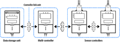
ZS-MDC11/MDC41 multi controllers

Basic specifications are the same as those for the sensor controllers.

The following points, however, are different.

(1) Sensor heads cannot be connected.

(2) A maximum 9 of controllers can be connected. Control link units are required to connect controllers.

(3) Processing functions between controllers: Math functions

Controller link unit

Connection using the ZS-XCN

Data storage units

Sensor controllers

Model

ZS-DSU11

ZS-DSU41

Number of mounted censor heads

Cannot be connected

Number of connectable controllers

10 controllers max. (ZS-MDC: 1 controller, ZS-HLDC: 9 controllers max.)16

Connectable controllers

ZS-HLDC__, ZS-MDC__

External
interface

Connection method

Serial I/O: connector, other: pre-wired (standard cable length: 2 m)

Serial I/O

USB 2.0

1 port, full speed (12 Mbps), MINI-B

RS-232C

1 port, 115,200 bps max.

Outputs

3 outputs: HIGH, PASS, and LOW

NPN open-collector, 30 VDC, 50 mA max.,
residual voltage: 1.2 V max.

3 outputs: HIGH, PASS, and LOW

PNP open-collector, 50 mA max.,
residual voltage: 1.2 V max.

Inputs

ON: Short-circuited with 0V terminal or 1.5 V or less

OFF: Open (leakage current: 0.1 mA max.)

ON: Short-circuited to supply voltage or within 1.5 V of supply voltage

OFF: Open (leakage current: 0.1 mA max.)

Data resolution

32 bits

Functions

Logging trigger functions

Start and stop triggers can be set separately; external triggers, data triggers (self-triggers), and time triggers

Other functions

External banks, alarm outputs, saved data format customization, and clock

Status indicators

OUT (orange), PWR (green), ACCESS (orange), and ERR (red)

Segment display

8-segment green LEDs, 6 digits

LCD

16 digitsx2 rows, color of characters: green, resolution per character: 5x8 pixel matrix

Setting inputs

Setting keys

Direction keys (UP, DOWN, LEFT, and RIGHT), SET key, ESC key, MENU key, and function keys (1 to 4)

Slide switch

Threshold switch (2 states: High/Low), mode switch (3 states: FUN, TEACH, and RUN)

Power supply voltage

21.6 V to 26.4 VDC (including ripple)

Current consumption

0.5 A max.

Ambient temperature

Operating: 0 to 50°C, storage: -15 to 60°C (with no icing or condensation)

Ambient humidity

Operating and storage: 35% to 85% (with no condensation)

Materials

Case: Polycarbonate (PC)

Weight

Approx. 280 g (excluding packing materials and accessories)

Accessories

Ferrite core (1) instruction sheet, tools for data storage unit: CSV file converter for data storage unit, smart analyzer macro edition
(Excel macros for analysis of collected data)


1. Refer to the table of ratings and specifications for details.

2. Refer to the table of ratings and specifications for details.

3. This is the peak-to-peak displacement conversion value in the displacement output at the measuring center distance in high-precision mode when the number of samples to average is set to 128 and the measuring mode is set to the high-resolution mode. The standard workpiece is white aluminum ceramics in diffuse reflection mode and glass in the regular reflection mode.

4. Up to two ZS-XC_B cables can be connected (22 m max.).

5. A robot cable (ZS-XC5BR) is also available.

6. Defined as 1/e² (13.5%) of the center optical intensity at the actual measurement center distance (effective value). The beam diameter is sometimes influenced by the ambient conditions of the workpiece, such as leaked light from the main beam.

7. This is the error in the measured value with respect to an ideal straight line. The standard workpiece is white aluminum ceramics in diffuse reflection mode and glass in the regular reflection mode of the ZS-LD20T/40T/50. Linearity may change according to the workpiece.

8. This is the peak-to-peak displacement conversion value in the displacement output at the measuring center distance in high-precision mode when the number of samples to average is set to 128 and the measuring mode is set to the high-resolution mode. The standard workpiece is white aluminum ceramics in diffuse reflection mode and glass in the regular reflection mode.

9. This is the value obtained at the measuring center distance when the Sensor and workpiece are fixed by an aluminum jig.

10. This value is obtained when the measuring mode is set to the high-speed mode.

11. Defined as 1/e² (13.5%) of the center optical intensity at the actual measurement center distance (effective value). The beam diameter is sometimes influenced by the ambient conditions of the workpiece, such as leaked light from the main beam.

12. This is the error in the measured value with respect to an ideal straight line. The standard workpiece is white aluminum ceramics in diffuse reflection mode and glass in the regular reflection mode of the ZS-LD20T/40T/50. Linearity may change according to the workpiece.

13. This is the peak-to-peak displacement conversion value in the displacement output at the measuring center distance in high-precision mode when the number of samples to average is set to 128 and the measuring mode is set to the high-resolution mode. The standard workpiece is white aluminum ceramics in diffuse reflection mode and glass in the regular reflection mode.

14. This is the value obtained at the measuring center distance when the sensor and workpiece are fixed by an aluminum jig.

15. This value is obtained when the measuring mode is set to the high-speed mode.

16. Control link units are required to connect controllers.

*1 Defined as 1/e² (13.5%) of the center optical intensity in the measurement center distance. The beam diameter is sometimes influenced by the ambient conditions of the workpiece such as leaked light from the main beam.

*2 This is the error on the measured value with respect to an ideal straight line. Linear curve may change according to the workpiece. The following lists the workpieces

*3 This is the “peak-to-peak” displacement conversion value of the displacement output in the measurement center distance when high-resolution mode and the average number in the table are set (For ZS-HLDS60, the maximum resolution at 250 mm is also included). The following lists the workpieces.

*4 Value obtained when the sensor part and object part are fixed with an aluminum jig.

1. Refer to the table of ratings and specifications for details.

2. Refer to the table of ratings and specifications for details.

3. This is the peak-to-peak displacement conversion value in the displacement output at the measuring center distance in high-precision mode when the number of samples to average is set to 128 and the measuring mode is set to the high-resolution mode. The standard workpiece is white aluminum ceramics in diffuse reflection mode and glass in the regular reflection mode.

4. Up to two ZS-XC_B cables can be connected (22 m max.).

5. A robot cable (ZS-XC5BR) is also available.

6. Defined as 1/e² (13.5%) of the center optical intensity at the actual measurement center distance (effective value). The beam diameter is sometimes influenced by the ambient conditions of the workpiece, such as leaked light from the main beam.

7. This is the error in the measured value with respect to an ideal straight line. The standard workpiece is white aluminum ceramics in diffuse reflection mode and glass in the regular reflection mode of the ZS-LD20T/40T/50. Linearity may change according to the workpiece.

8. This is the peak-to-peak displacement conversion value in the displacement output at the measuring center distance in high-precision mode when the number of samples to average is set to 128 and the measuring mode is set to the high-resolution mode. The standard workpiece is white aluminum ceramics in diffuse reflection mode and glass in the regular reflection mode.

9. This is the value obtained at the measuring center distance when the Sensor and workpiece are fixed by an aluminum jig.

10. This value is obtained when the measuring mode is set to the high-speed mode.

11. Defined as 1/e² (13.5%) of the center optical intensity at the actual measurement center distance (effective value). The beam diameter is sometimes influenced by the ambient conditions of the workpiece, such as leaked light from the main beam.

12. This is the error in the measured value with respect to an ideal straight line. The standard workpiece is white aluminum ceramics in diffuse reflection mode and glass in the regular reflection mode of the ZS-LD20T/40T/50. Linearity may change according to the workpiece.

13. This is the peak-to-peak displacement conversion value in the displacement output at the measuring center distance in high-precision mode when the number of samples to average is set to 128 and the measuring mode is set to the high-resolution mode. The standard workpiece is white aluminum ceramics in diffuse reflection mode and glass in the regular reflection mode.

14. This is the value obtained at the measuring center distance when the sensor and workpiece are fixed by an aluminum jig.

15. This value is obtained when the measuring mode is set to the high-speed mode.

16. Control link units are required to connect controllers.

En quoi pouvons-nous vous aider ?

Pour toute question ou demande de devis, veuillez nous contacter ou envoyer une demande.

0825 825 679
Contactez-nous

Contactez-moi ZS-HL

zs-hl prod

Merci de compléter tous les champs *. Les informations sont traitées de manière confidentielle.

Text error notification

Text error notification

Text error notification

Text error notification

Text error notification

Country error notification

Text area error notification

Checkbox error notification

Checkbox error notification

Merci de votre demande. Nous reviendrons vers vous dès que possible.

Nous rencontrons des problèmes techniques. Votre demande ne peut être traitée. Veuillez nous excuser et ré-essayer plus tard. Détails :

Download
0825 825 679
0825 825 679
Demander un devis
Demander un devis

Devis pour ZS-HL

Vous pouvez utiliser ce formulaire pour demander un devis sur le produit de votre choix. Merci de compléter tous les champs *. Les informations sont traitées de manière confidentielle.

zs-hl prod

Détails personnels

ZS-HL

Text error notification

Text error notification

Text error notification

Text error notification

Country error notification

Détails du devis

Select notification error

Select notification error

Text area error notification

Checkbox error notification

Checkbox error notification

Merci de votre demande. Nous vous enverrons l'information demandée au plus tôt.

Nous rencontrons des problèmes techniques. Votre demande ne peut être traitée. Veuillez nous excuser et ré-essayer plus tard. Détails :

Download
Demander un devis
Demander un devis

Fonctions

Mesure de distance - Surface d'un disque

Sur les surfaces extrêmement réfléchissantes, le capteur vérifie le polissage d'un disque en mesurant avec précision la distance.

Épaisseur du verre - Pare-brise

Le ZS est capable de mesurer l'épaisseur d'un objet transparent grâce à une seule tête de détection.

Mesure de la hauteur - Cordon de colle

Le capteur mesure avec précision la hauteur d'un cordon de colle semi-transparent.

Mesure de l’épaisseur - Caoutchouc noir

Le ZS mesure l'épaisseur d'un matériau caoutchouteux noir mat à l'aide de deux capteurs et d'une unité de calcul.

Inspection de planéité - Piston

Plusieurs capteurs vérifient la planéité d'une surface réfléchissante usinée.

Téléchargements

download
EAC Mark removal Avis d'interruption
enPDF 221 ko
download
ZS Compoway/F Manuel de communications
enPDF 1,46 Mo
download
ZS Non-procedual Manuel de communications
enPDF 1,89 Mo
download
ZS-DSU Manuel d'utilisation
frPDF 5,38 Mo
download
ZS-HL Manuel d'utilisation
frPDF 15,5 Mo
download
ZS-L Manuel d'utilisation
enPDF 3,77 Mo