ZX-GT
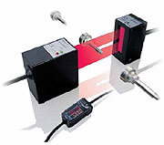
Micromètre laser intelligent : précis et rapide sur toutes les surfaces
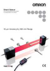
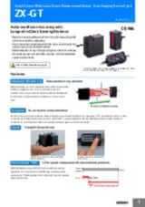
Le nouveau micromètre laser intelligent ZX-GT vient compléter la plate-forme de mesure laser intelligente d’Omron. Le ZX-GT peut détecter des contours, mesurer des diamètres d’objets et calculer, de manière précise, la position de toutes sortes de matériaux. Basé sur la technologie CCD, le ZX-GT fonctionne avec une très haute précision et une grande rapidité même dans des conditions environnementales difficiles. Les objets transparents, les surfaces réfléchissantes ou bien encore des positions changeantes n’ont aucune influence sur les résultats. Le logiciel PC Smart Monitor vous aidera à installer et à configurer votre micromètre laser intelligent.
- Haute précision : 5 à 10 µm
- Toutes surfaces
- Longue portée : < 500 mm
- Largeur de ligne allant jusqu’à 28 mm
Caractéristiques et références
Ordering information
Sensors
Controller
Accessories (order separately)
Set of interface unit and setup software PCs
Interface unit(RS-232C/binary output)
Setup software PCs
Calculating units
Receiver-controller extension cable
Specifications
Sensor
|
Visible semiconductor laser diode (wavelength 650 nm, CLASS 1 of EN60825-1/IEC60825-1, CLASS of FDA(21CFR 1040.10 and 1040.11) |
||||
|
2
2.
Linearity is given to be a typical error with respect to an ideal straight line when the distance between the emitter and receiver is 100 mm and light is blocked at a distance of 50 mm from the receiver. (On the ZX-GT2840_, the measurement object is measured at a distance of 20 mm from the receiver.)
|
||||
|
ON: Short-circuited with 0 V or 1.5 V max. |
ON: Short-circuited with power supply voltage or |
|||
|
NPN open-collector output |
PNP open-collector output |
|||
|
Operating: 0 to 40°C, storage: -15 to 50°C (with no icing or condensation) |
||||
|
10 to 150 Hz single-amplitude: 0.75 mm for 80 min each in X, Y and Z directions |
||||
Controller
|
1.5 ms (standard mode (NORM)) |
|||
|
For current output: 4 to 20 mA/F.S., max. load resistance 300
Ω
|
|||
|
Timing input, bank switching input, zero reset input, reset input |
ON: short-circuited with 0 V or 1.5 V max. |
ON: short-circuited with power supply voltage or |
|
|
Sync output
11
11.
Normally, wire the sync output wire directly to the emitter's sync input wire and run the controller in the standard mode. On an NPN type controller, use an NPN type emitter, and on a PNP type controller, use a PNP type emitter. Wiring of the sync wires is not required when the controller is run in the high-speed mode.
(Note, however, that the controller becomes more susceptible to the influence of ambient light in this case.) |
NPN open-collector output |
PNP open-collector output |
|
|
Judgment output indicator: HIGH (orange), PASS (green), LOW (orange) |
|||
|
Interrupted beam width measurement, incident beam width measurement, outer diameter measurement, center position measurement, IC lead pitch, |
|||
|
Measured value, resolution, threshold, voltage output value, current output value (number of display digits can be changed) |
|||
|
Sample hold, peak hold, bottom hold, peak-to-peak hold, average hold, delay hold |
|||
|
Optical axis adjust mode/light intensityt writing mode, variable binary level, variable edge filter, analog output scaling |
|||
|
2 possible on up to two controllers (calculation Unit ZX-CAL2 is required for connecting controllers to each other.) A-B, A+B, width |
|||
|
Measurement cycle setting, threshold setting, hysteresis setting, initialization, key lock |
|||
|
Operating: 0 to 50°C, storage: -15 to 60°C (with no icing or condensation) |
|||
|
10 to 150 Hz single-amplitude: 0.35 mm for 80 min each in X, Y and Z directions |
|||
|
Case: PBT (polybutylene terephthalate), cover: Polycarbonate |
|||
Interface unit
1. Distance between emitter and receiver: 500 mm, measurement object at 250 mm from receiver. Glass ends of chamfer 0.1 mm or more can be detected in glass edge measurement mode. (at binary level 70%)
2. Linearity is given to be a typical error with respect to an ideal straight line when the distance between the emitter and receiver is 100 mm and light is blocked at a distance of 50 mm from the receiver. (On the ZX-GT2840_, the measurement object is measured at a distance of 20 mm from the receiver.)
3. The amount of fluctuation (±3 σ ) in the analog output when the distance between the emitter and receiver is 100 mm and a ZX-GTC_ is connected
4.
Change in the light cutoff value on one side when the distance between the emitter and receiver is 100 mm and the light is half-cutoff at a distance of 50 mm from the receiver (On the
ZX-GT2840_, the measurement object is measured at a distance of 20 mm from the receiver.)
6. The first response time is “measurement cycle x (number of samples to average setting + 1) + 1 ms” max. For the second response time onwards, the specified measurement cycle time is output.
7. The response time in the high-speed mode (FAST) for the IC lead pitch and IC lead width judgment modes is 1 ms.
11.
Normally, wire the sync output wire directly to the emitter's sync input wire and run the controller in the standard mode. On an NPN type controller, use an NPN type emitter, and on a PNP type controller, use a PNP type emitter. Wiring of the sync wires is not required when the controller is run in the high-speed mode.
(Note, however, that the controller becomes more susceptible to the influence of ambient light in this case.)
En quoi pouvons-nous vous aider ?
Pour toute question ou demande de devis, veuillez nous contacter ou envoyer une demande.
Contactez-moi ZX-GT
Merci de votre demande. Nous reviendrons vers vous dès que possible.
Nous rencontrons des problèmes techniques. Votre demande ne peut être traitée. Veuillez nous excuser et ré-essayer plus tard. Détails :
DownloadDevis pour ZX-GT
Vous pouvez utiliser ce formulaire pour demander un devis sur le produit de votre choix. Merci de compléter tous les champs *. Les informations sont traitées de manière confidentielle.
Merci de votre demande. Nous vous enverrons l'information demandée au plus tôt.
Nous rencontrons des problèmes techniques. Votre demande ne peut être traitée. Veuillez nous excuser et ré-essayer plus tard. Détails :
DownloadTéléchargements