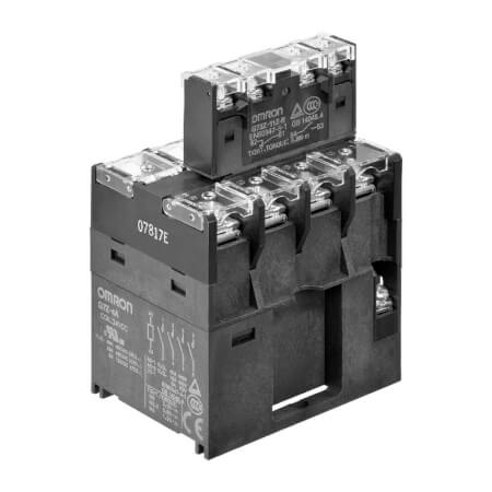
Connexion

Nous rencontrons des problèmes techniques. Votre demande ne peut être traitée. Veuillez nous excuser et ré-essayer plus tard. Détails :

Download

Inscription

Nous rencontrons des problèmes techniques. Votre demande ne peut être traitée. Veuillez nous excuser et ré-essayer plus tard. Détails :

Download

Merci pour votre inscription à Omron

Un e-mail qui vous permettra de terminer la création de votre compte a été envoyé à

Revenir au site Web

obtenir un accès direct

Veuillez remplir le formulaire ci-dessous pour accéder directement au contenu de cette page.

Text error notification

Text error notification

Checkbox error notification

Checkbox error notification

Nous rencontrons des problèmes techniques. Votre demande ne peut être traitée. Veuillez nous excuser et ré-essayer plus tard. Détails :

Download

Nous vous remercions de votre intérêt.

Vous avez désormais accès à G7Z

Un email de confirmation a été envoyé à

Continuer vers la page

Veuillez vous ou obtenir un accès direct pour télécharger ce document.

G7Z

G7Z

Relais de puissance compact commutant jusqu'à 160 A

La gamme G7Z offre une solution compacte et économique pour des applications comme les variateurs, onduleurs et les circuits de batteries solaires ou à pile à combustible. Le relais en combinaison avec le bloc contacts auxiliaire est conforme à la norme EN 60947-4-1. Les bobines sont disponibles en 12 ou 24 Vc.c. La consommation est inférieure à 4 W.

  • Courant commuté de 160 A (40 A / 4 pôles / IEC-AC1)
  • Tension commutée de 440 Vc.a.
  • Conforme à la norme PV européenne (VDE0126)
  • Consommation inférieure à 4 W.
  • Faible bruit de commutation (70 db)

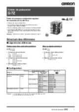
Caractéristiques et références

Ordering Information

Relay with Auxiliary Contact Block

Number of poles
(Relay with Auxiliary Contact)
Contact configuration Contact Mechanism of Auxiliary Contacts
Relay Auxiliary Contact Block Single-break models Double-break models
2
Scheduled to close the order at the end of March 2019.
Rated Voltage Order code Rated Voltage Order code
4 poles + 2 poles 4PST-NO DPST-NO 12, 24 VDC G7Z-4A-20Z-R 12, 24 VDC G7Z-4A-20Z
SPST-NO/SPST-NC 12, 24 VDC G7Z-4A-11Z-R 12, 24 VDC G7Z-4A-11Z
DPST-NC 12, 24 VDC G7Z-4A-02Z-R 12, 24 VDC G7Z-4A-02Z
3PST-NO/SPST-NC DPST-NO 12, 24 VDC G7Z-3A1B-20Z-R 12, 24 VDC G7Z-3A1B-20Z
SPST-NO/SPST-NC 12, 24 VDC G7Z-3A1B-11Z-R 12, 24 VDC G7Z-3A1B-11Z
DPST-NC 12, 24 VDC G7Z-3A1B-02Z-R 12, 24 VDC G7Z-3A1B-02Z
DPST-NO/DPST-NC DPST-NO 12, 24 VDC G7Z-2A2B-20Z-R 12, 24 VDC G7Z-2A2B-20Z
SPST-NO/SPST-NC 12, 24 VDC G7Z-2A2B-11Z-R 12, 24 VDC G7Z-2A2B-11Z
DPST-NC 12, 24 VDC G7Z-2A2B-02Z-R 12, 24 VDC G7Z-2A2B-02Z
Note:
  1. Relay contact terminals are M5, and the coil terminals are M3.5.
  2. Auxiliary contact block terminals are M3.5.
  3. When placing an order, specify the model number and rated supply voltage (12 VDC or 24 VDC).

Relay

Number of poles Contact configuration Rated Voltage Order code
4 poles 4PST-NO 12, 24 VDC G7Z-4A
3PST-NO/SPST-NC G7Z-3A1B
DPST-NO/DPST-NC G7Z-2A2B
Note:
  1. Relay contact terminals are M5, and the coil terminals are M3.5.
  2. When placing an order, specify the model number and rated supply voltage (12 VDC or 24 VDC).

Accessories (Order Separately)

Auxiliary Contact Block

Number of poles Contact Configuration Order code
Contact Mechanism of Auxiliary Contacts
Single-break models Double-break models
2
Scheduled to close the order at the end of March 2019.
2 poles DPST-NO G73Z-20Z-R G73Z-20Z
SPST-NO/SPST-NC G73Z-11Z-R G73Z-11Z
DPST-NC G73Z-02Z-R G73Z-02Z
Note:

Auxiliary contact block terminals are M3.5.

Specifications

Coil ratings

Rated voltage Rated current (mA) Coil resistance (Ω) Must operate voltage Must release voltage Maximum voltage Power consumption (W)
Percentage of rated voltage
12 VDC 308 39 75% max. 10% min. 110% Approx. 3.7
24 VDC 154 156
Note:
  1. Rated current and coil resistance were measured at a coil temperature of 23°C with coil resistance of ±15%.
  2. Operating characteristics were measured at a coil temperature of 23°C.
  3. The maximum allowable voltage is the maximum value of the fluctuation range for the Relay coil operating power supply
    and was measured at an ambient temperature of 23°C. There is, however, no continuous allowance.

Contact ratings

Relay, Relay with Auxiliary Contact Block

Model G7Z-4A-Z(-R), G7Z-3A1B-Z(-R), G7Z-2A2B-Z(-R)
Load Resistive load Inductive load cosφ = 0.3 Resistive load L/R = 1 ms
Contact structure Double break
Contact material Ag alloy
Rated load NO 40 A at 440 VAC 22 A at 440 VAC 5 A at 110 VDC
NC 25 A at 440 VAC 10 A at 440 VAC 5 A at 110 VDC
Rated carry current NO 40 A
2
Set of Relay and Auxiliary Contact Block: 45 to 60°C; for the continuous carry current, reduce 40 A by 0.7 A/°C.
NC 25 A
Maximum contact voltage 480 VAC 125 VDC
Maximum contact current NO 40 A 22 A 5 A
NC 25 A 10 A 5 A
Maximum switching capacity NO 17,600 VA 9,680 VA 550 W
NC 11,000 VA 4,400 VA 550 W
Failure rate P value (reference value) 2 A at 24 VDC
Note:

The ratings for the auxiliary contact block mounted on the G7Z are the same as those for the G73Z auxiliary contact block.

Auxiliary Contact Block

Model G73Z-20Z-R, G73Z-11Z-R, G73Z-02Z-R G73Z-20Z, G73Z-11Z, G73Z-02Z
Load Resistive load Inductive load
cosφ = 0.3
Resistive load
L/R = 1 ms
Resistive load Inductive load
cosφ = 0.3
Resistive load
L/R = 1 ms
Contact structure Single break Double break
Contact material Au clad + AgNi Au clad + Ag
Rated load 1 A at 440 VAC 0.5 A at 440 VAC 0.5 A at 110 VDC 1 A at 440 VAC 0.5 A at 440 VAC 0.5 A at 110 VDC
Rated carry current 1 A 1 A
Maximum contact voltage 480 VAC 125 VDC 480 VAC 125 VDC
Maximum contact current 1 A 0.5 A 1 A 0.5 A
Maximum switching capacity 440 VA 220 VA 55 W 440 VA 220 VA 55 W
Failure rate P value (reference value) 1 mA at 1 VDC 1 mA at 5 VDC

Characteristics

Classification Relay with
auxiliary contact block
2
The specifications for the auxiliary contact block mounted on the G7Z are the same as those for the G73Z auxiliary contact block.
Auxiliary contact block
Model G7Z-4A-⬜Z(-R), G7Z-3A1B-⬜Z(-R), G7Z-2A2B-⬜Z(-R) G73Z-20Z-R, G73Z-11Z-R, G73Z-02Z-R G73Z-20Z, G73Z-11Z, G73Z-02Z
Contact resistance
2
The contact resistance for the Relay (G7Z) was measured with 1 A at 5 VDC using the voltage drop method.
The contact resistance for the auxiliary contact block (G73Z) was measured with 0.1 A at 5 VDC using the voltage drop method.
400 mΩ max. 100 mΩ max.
Operating time
2
The operate time was measured with the rated voltage imposed with any contact bounce ignored at the ambient temperature of 23°C.
50 ms max.
Release time
2
The operate time was measured with the rated voltage imposed with any contact bounce ignored at the ambient temperature of 23°C.
50 ms max.
Maximum operating frequency Mechanical 1,800 operations/h
Rated load 1,200 operations/h
Insulation resistance
2
The insulation resistance was measured with a 1,000-VDC megohmmeter applied to the same places as those used for checking the dielectric strength.
1,000 MΩ min.
Dielectric strength Between coil and contacts 4,000 VAC, 50/60 Hz for 1 min
Between contacts of different polarity 4,000 VAC, 50/60 Hz for 1 min
Between contacts of the same polarity 2,000 VAC, 50/60 Hz for 1 min
Impulse withstand voltage Between coil and contacts 10 kV, 1.2 × 50 µs
Between contacts of different polarity 10 kV, 1.2 × 50 µs
Between contacts of the same polarity 4.5 kV, 1.2 × 50 µs 3.0 kV, 1.2 × 50 µs 4.5 kV, 1.2 × 50 µs
Vibration resistance Destruction 10 to 55 to 10 Hz, 0.5-mm single amplitude (1.0-mm double amplitude)
Malfunction NO: 10 to 55 to 10 Hz, 0.5-mm single amplitude (1.0-mm double amplitude) NC: 10 to 32 to 10 Hz, 0.5-mm single amplitude (1.0-mm double amplitude)
Shock resistance Destruction Screw mounting: 700 m/s2, DIN Track mounting: 500 m/s2
Malfunction NO: 100 m/s2 NC: 25 m/s2
Durability Mechanical 1,000,000 operations min. (at 1,800 operations/h, contact no load)
Electrical
2
The electrical endurance was measured at an ambient temperature of 23°C.
AC resistive load: 80,000 operations
AC inductive load: 80,000 operations
DC resistive load: 100,000 operations
(at 1,200 operations/h, rated load)
Failure rate (P level) (reference value)
2
The failure rate is based on an operating frequency of 1,800 operations/h.
2 A at 24 VDC 1 mA at 1 VDC 1 mA at 5 VDC
Ambient operating temperature −25 to 60°C (with no icing or condensation)
Ambient operating humidity 5% to 85%
Weight Approx. 330 g Approx. 18 g
Note:

The above values are initial values.

En quoi pouvons-nous vous aider ?

Pour toute question ou demande de devis, veuillez nous contacter ou envoyer une demande.

0825 825 679
Contactez-nous

Contactez-moi G7Z

G7Z-4A-11Z-R-24VDC

Merci de compléter tous les champs *. Les informations sont traitées de manière confidentielle.

Text error notification

Text error notification

Text error notification

Text error notification

Text error notification

Country error notification

Text area error notification

Checkbox error notification

Checkbox error notification

Merci de votre demande. Nous reviendrons vers vous dès que possible.

Nous rencontrons des problèmes techniques. Votre demande ne peut être traitée. Veuillez nous excuser et ré-essayer plus tard. Détails :

Download
0825 825 679
0825 825 679
Demander un devis
Demander un devis

Devis pour G7Z

Vous pouvez utiliser ce formulaire pour demander un devis sur le produit de votre choix. Merci de compléter tous les champs *. Les informations sont traitées de manière confidentielle.

G7Z-4A-11Z-R-24VDC

Détails personnels

G7Z

Text error notification

Text error notification

Text error notification

Text error notification

Country error notification

Détails du devis

Select notification error

Select notification error

Text area error notification

Checkbox error notification

Checkbox error notification

Merci de votre demande. Nous vous enverrons l'information demandée au plus tôt.

Nous rencontrons des problèmes techniques. Votre demande ne peut être traitée. Veuillez nous excuser et ré-essayer plus tard. Détails :

Download
Demander un devis
Demander un devis