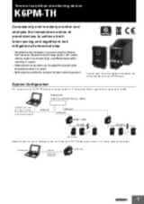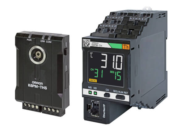
K6PM-TH
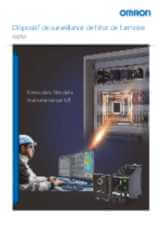
Surveillance d'état basée sur la thermographie
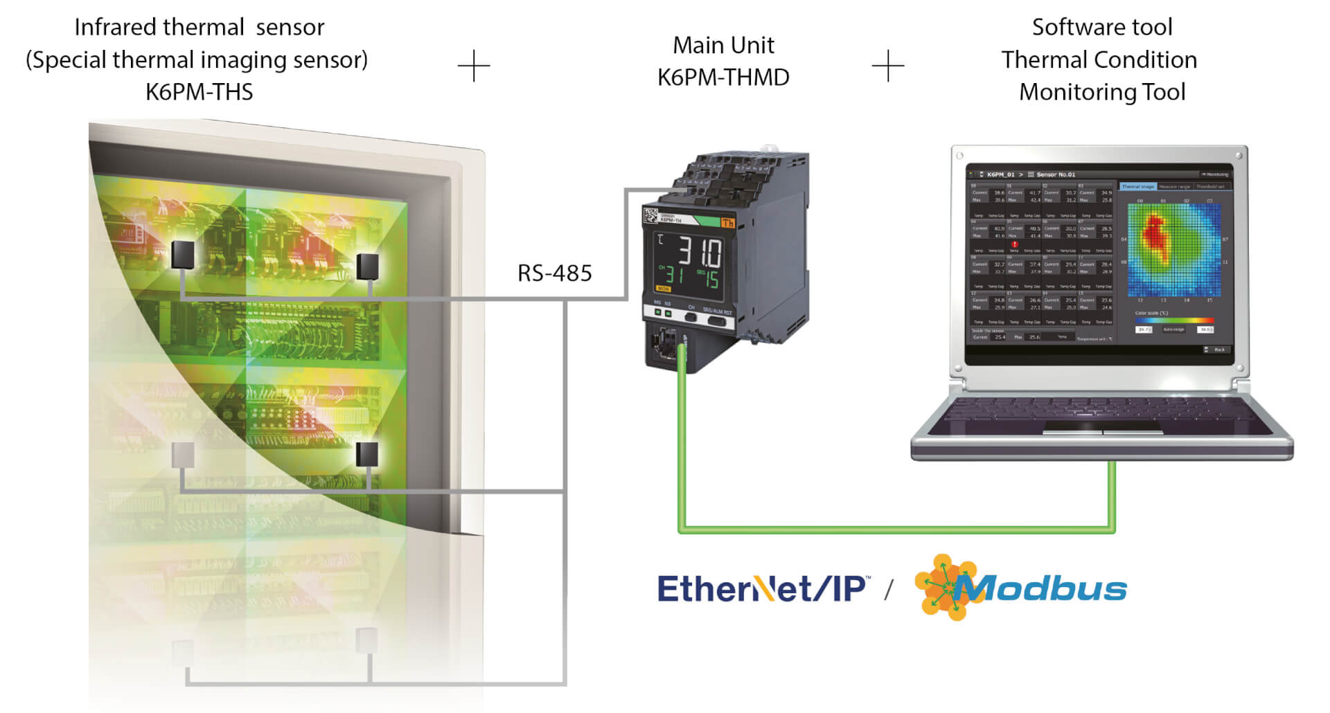
Le K6PM-TH mesure et surveille la température de surface à l'aide de 31 caméras infrarouges connectées, sous forme de thermographie continue.
- Surveiller et prévoir la tendance de la température, en émettant une alarme à chaque fois que la température d'une zone donnée est supérieure au seuil défini, ou qu'elle devrait prochainement atteindre une valeur critique
- Prendre en compte la tendance de température différentielle (entre l'environnement et l'objet mesuré), en émettant des alarmes uniquement en cas de conditions critiques.
- Définir automatiquement le seuil de température de chaque zone (chaque caméra divise la zone surveillée en 16 quadrants), en fonction des conditions de référence
- Notifications par e-mail en cas d'avertissement/d'alarme,
- Surveillance à distance
- Interaction avec les applications personnalisées et le serveur MQTT.
Caractéristiques et références
| Produit | Supply voltage AC | Supply voltage DC | Description | |
|---|---|---|---|---|
|
|
20.4-26.4 V | 20.4-26.4 V | Dispositif de surveillance de l'état thermique des armoires de commande et des panneaux, 24 VDC, sortie de commande transistor, Push-in Plus, LCD display, EtherNet/IP et Modbus TCP |
|
Besoin d'aide ?
Nous sommes là pour vous aider ! Contactez-nous et nos spécialistes vous aideront à trouver la meilleure solution pour votre entreprise.
Contactez-moi K6PM-TH

Merci de votre demande. Nous reviendrons vers vous dès que possible.
Nous rencontrons des problèmes techniques. Votre demande ne peut être traitée. Veuillez nous excuser et ré-essayer plus tard. Détails :
DownloadDevis pour K6PM-TH
Vous pouvez utiliser ce formulaire pour demander un devis sur le produit de votre choix. Merci de compléter tous les champs *. Les informations sont traitées de manière confidentielle.
Merci de votre demande. Nous vous enverrons l'information demandée au plus tôt.
Nous rencontrons des problèmes techniques. Votre demande ne peut être traitée. Veuillez nous excuser et ré-essayer plus tard. Détails :
DownloadFeature
Le K6PM est un partenaire fiable pour surveiller les armoires critiques des installations, ainsi que les armoires d'équipement tout au long de leur vie (développement, validation, tests d'installation en usine et post-installation).
Particulièrement adapté aux applications dont l'armoire est située juste à côté d'une machine générant une chaleur intense (fournaises, fours, machines de moulage).
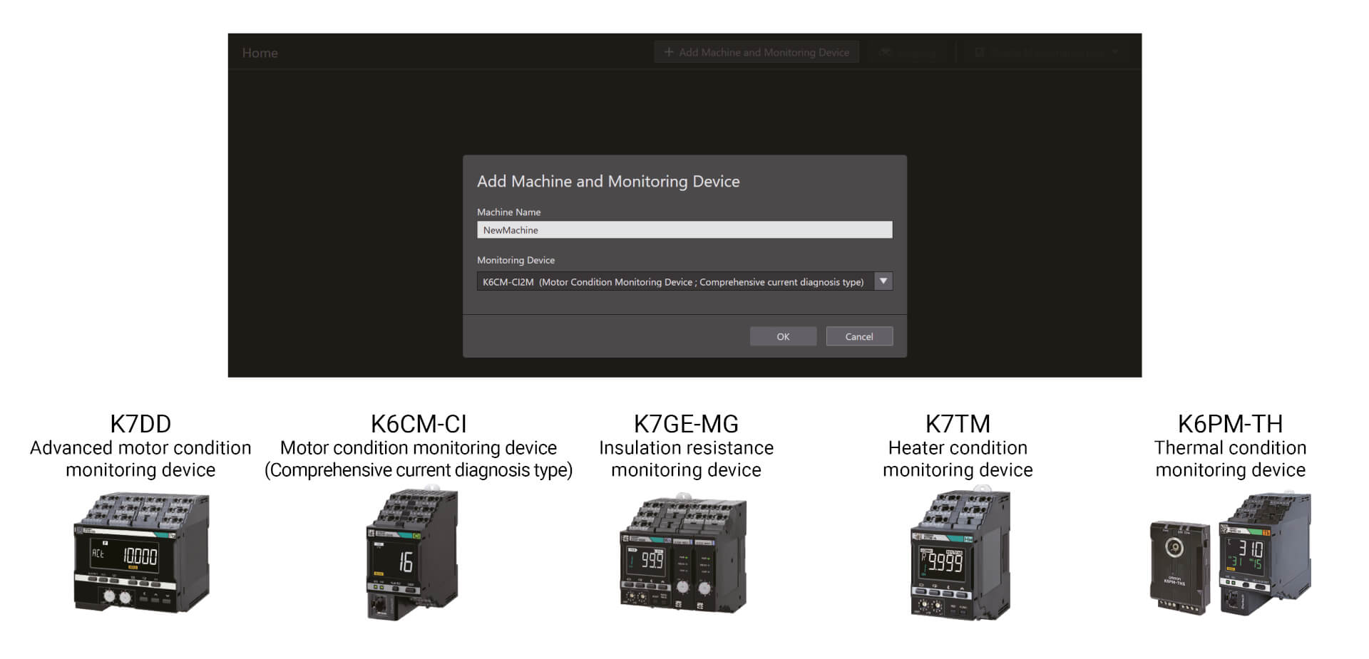
Les dispositifs de surveillance de l'état peuvent être configurés avec un seul outil
Avec une configuration facile en trois étapes, l'outil de configuration de surveillance de l'état permet la configuration par lots d'une large gamme de dispositifs de surveillance de l'état, tels que ceux pour la surveillance des moteurs, des températures, de l'isolation et des éléments chauffants. Il peut être utilisé sans compétences particulières, réduisant ainsi les besoins de formation
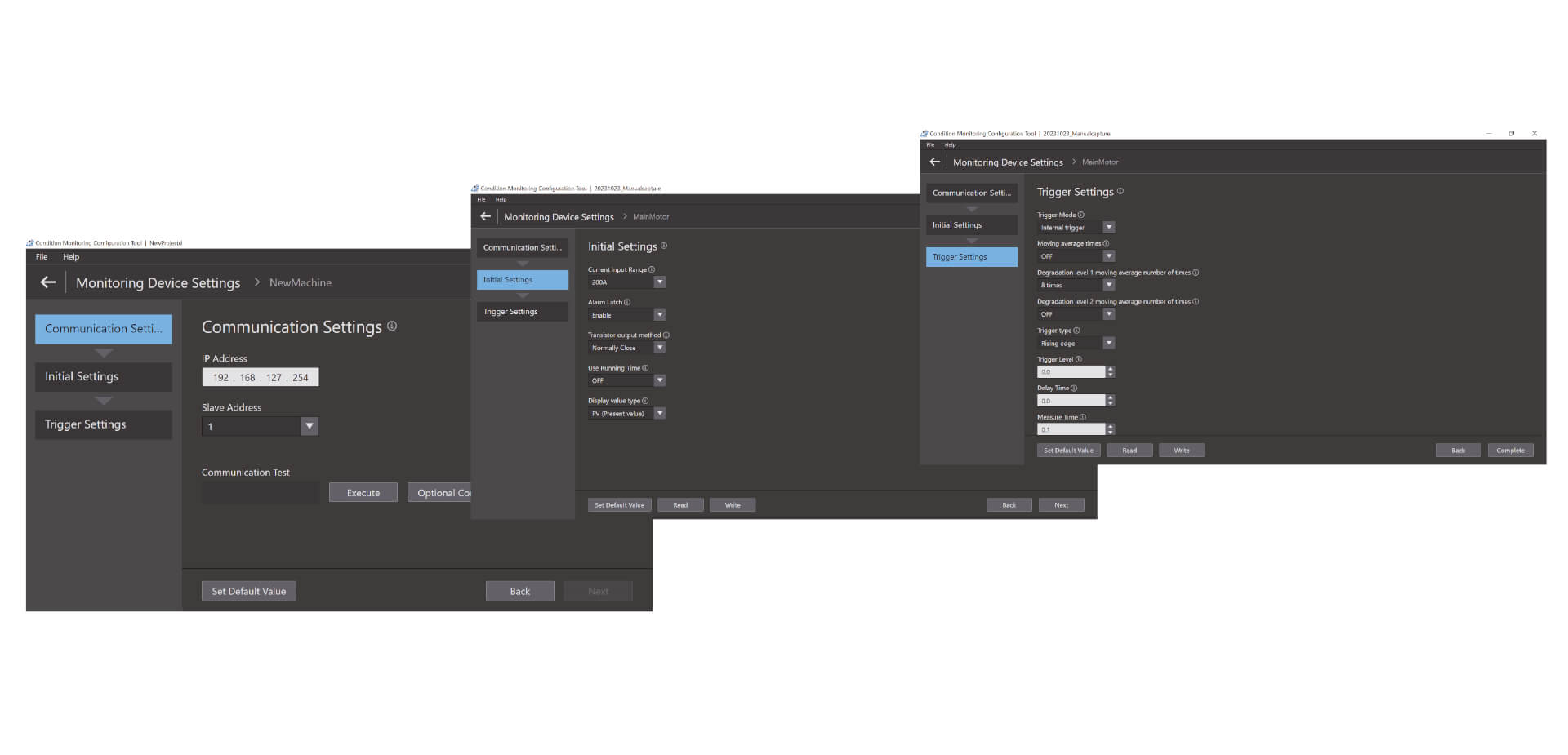
Une configuration facile en trois étapes
L'outil de configuration de surveillance de l'état permet la configuration par lots d'une large gamme de dispositifs de surveillance de l'état, tels que ceux pour la surveillance des moteurs, des températures, de l'isolation et des éléments chauffants. Il peut être utilisé sans compétences particulières, réduisant ainsi les besoins de formation. La configuration s'effectue en trois étapes seulement : configuration des communications, configuration initiale et configuration du déclencheur.*1 Grâce à son fonctionnement avancé, cet outil améliore également la productivité sur site.
Vidéos
-
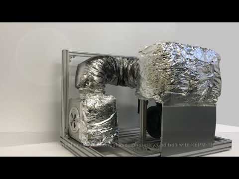
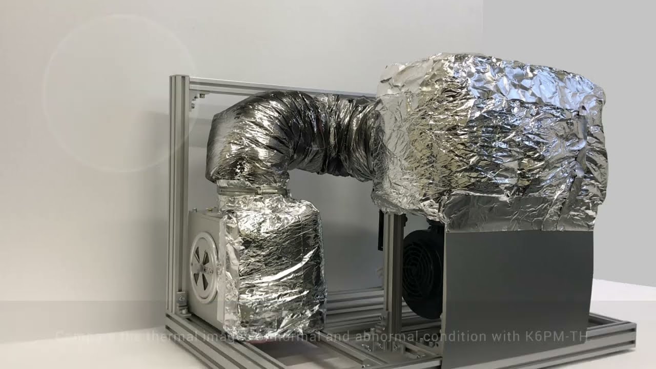
OMRON K6PM-TH Thermal Condition Monitor Detecting Dryer Duct Leak
Coating and drying is one of the most dangerous processes in car manufacturing. In the drying oven, air heated to 400°C in the combustion chamber travels through the air duct for use in drying. These air ducts degrade over time, sometimes allowing air hotter than 100°C to leak, which can lead to burn injuries during patrol inspection. #omronindustrialautomation #MakeitOMRON
02:59
OMRON K6PM-TH Thermal Condition Monitor Detecting Dryer Duct Leak
Coating and drying is one of the most dangerous processes in car manufacturing. In the drying oven, air heated to 400°C in the combustion chamber travels through the air duct for use in drying. These air ducts degrade over time, sometimes allowing air hotter than 100°C to leak, which can lead to burn injuries during patrol inspection. #omronindustrialautomation #MakeitOMRON
-
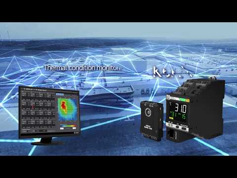
K6PM: Innovation in thermal monitoring and panel maintenance
Parts to check are increasing as devices and wires in a panel increase for high-functioned facilities and equipment. On the other hand, maintenance frequency is decreasing due to shortage of the maintenance engineers, resulting in a higher risk of accident. There are various causes of failures on the device. Current methods of manual inspections are useful but they only provide limited amount of failure detection information. Here is a new solution from OMRON.
02:37
K6PM: Innovation in thermal monitoring and panel maintenance
Parts to check are increasing as devices and wires in a panel increase for high-functioned facilities and equipment. On the other hand, maintenance frequency is decreasing due to shortage of the maintenance engineers, resulting in a higher risk of accident. There are various causes of failures on the device. Current methods of manual inspections are useful but they only provide limited amount of failure detection information. Here is a new solution from OMRON.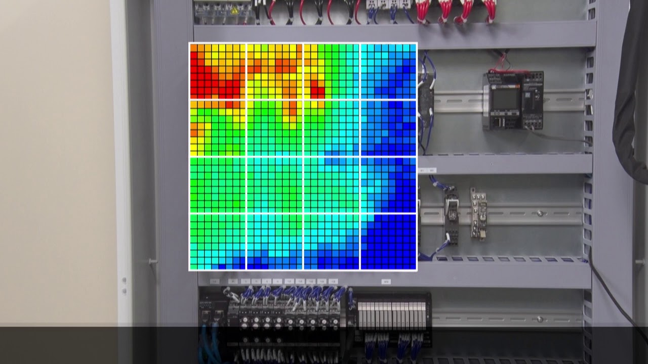
-

Omron K6PM "Auto threshold set" algorithm
The amount of heat generated varies from device to device. For this reason, the optimum threshold value for the thermal monitoring must be set depending on the device. K6PM can divide one sensor monitoring area into 16 segments and automatically set the threshold for each segment.
01:27
Omron K6PM "Auto threshold set" algorithm
The amount of heat generated varies from device to device. For this reason, the optimum threshold value for the thermal monitoring must be set depending on the device. K6PM can divide one sensor monitoring area into 16 segments and automatically set the threshold for each segment.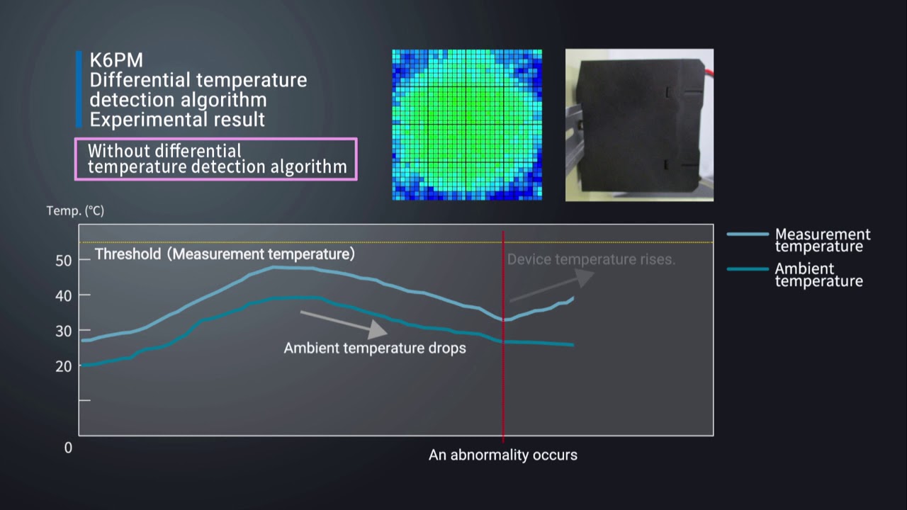
-

Omron K6PM "Differential temperature detection" algorithm
For applications where there are fluctuations in ambient temperature, it can be difficult to determine the cause of the temperature change of the device. The K6PM constantly monitors the difference between measure temperature and ambient temperature. This allows the K6PM to accurately detect abnormalities without being affected by ambient temperatures.
01:51
Omron K6PM "Differential temperature detection" algorithm
For applications where there are fluctuations in ambient temperature, it can be difficult to determine the cause of the temperature change of the device. The K6PM constantly monitors the difference between measure temperature and ambient temperature. This allows the K6PM to accurately detect abnormalities without being affected by ambient temperatures.


Solutions
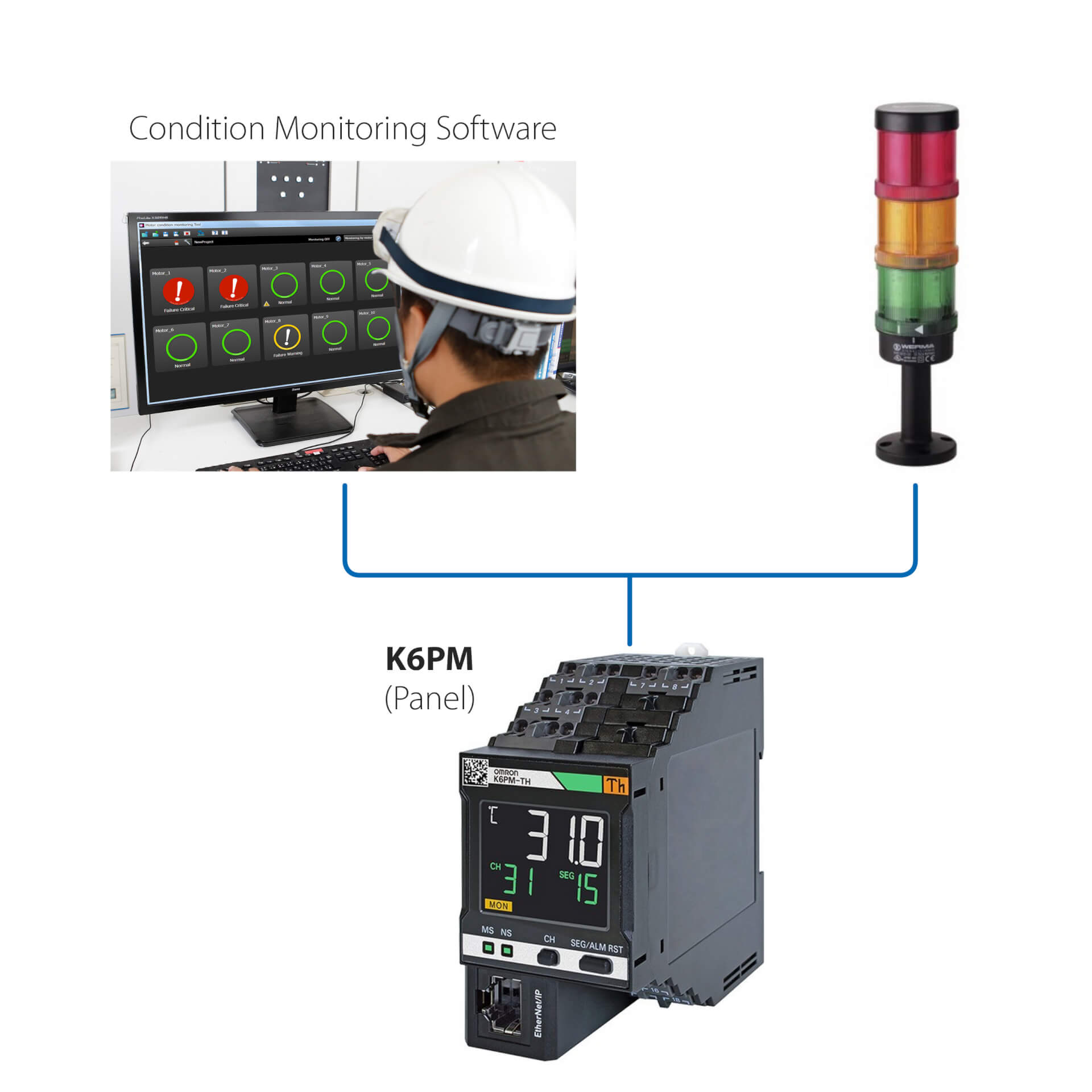
Installation autonome (sans API)
Avantages de cette solution simple :
- Surveiller l'état du moteur via la LED intégrée ou le logiciel de surveillance d'état
- Configurer les contrôleurs à l'aide du logiciel de contrôle d'état fourni avec l'appareil
- Interfacer le K6CM avec tout périphérique d'E/S externe (sortie num.)
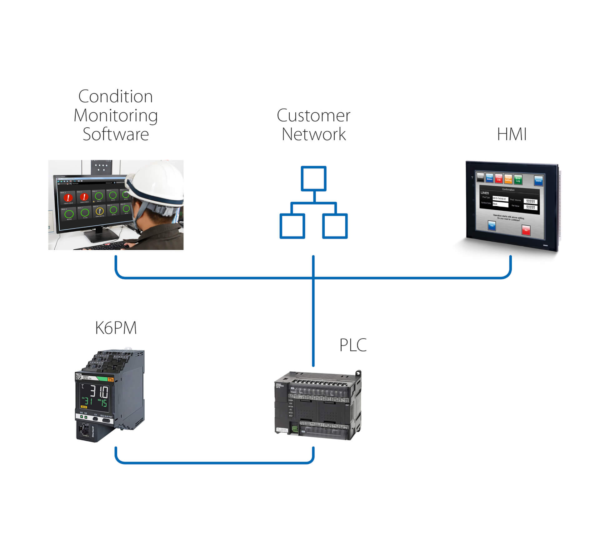
Installation autonome (avec API)
Cette solution permet, en plus de la solution précédente :
- De surveiller l'état du moteur jusqu'au logiciel de contrôle de condition, exécuté sur un PC connecté via une API
- D'utiliser la connexion à distance de l'API afin d'atteindre le K6PM pour la surveillance et la configuration à distance
- De déclencher, via l'API, des actions suite à tout avertissement/toute alarme détecté(e) par le K6PM
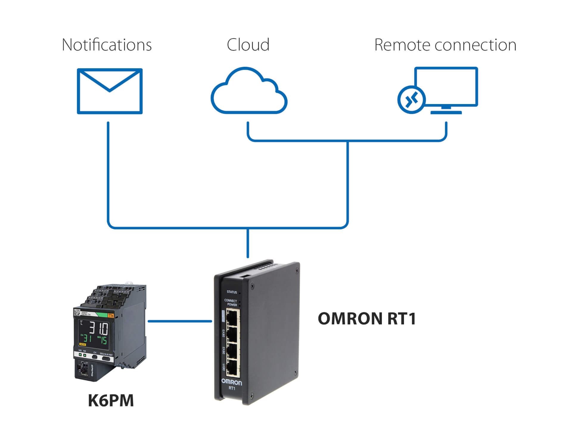
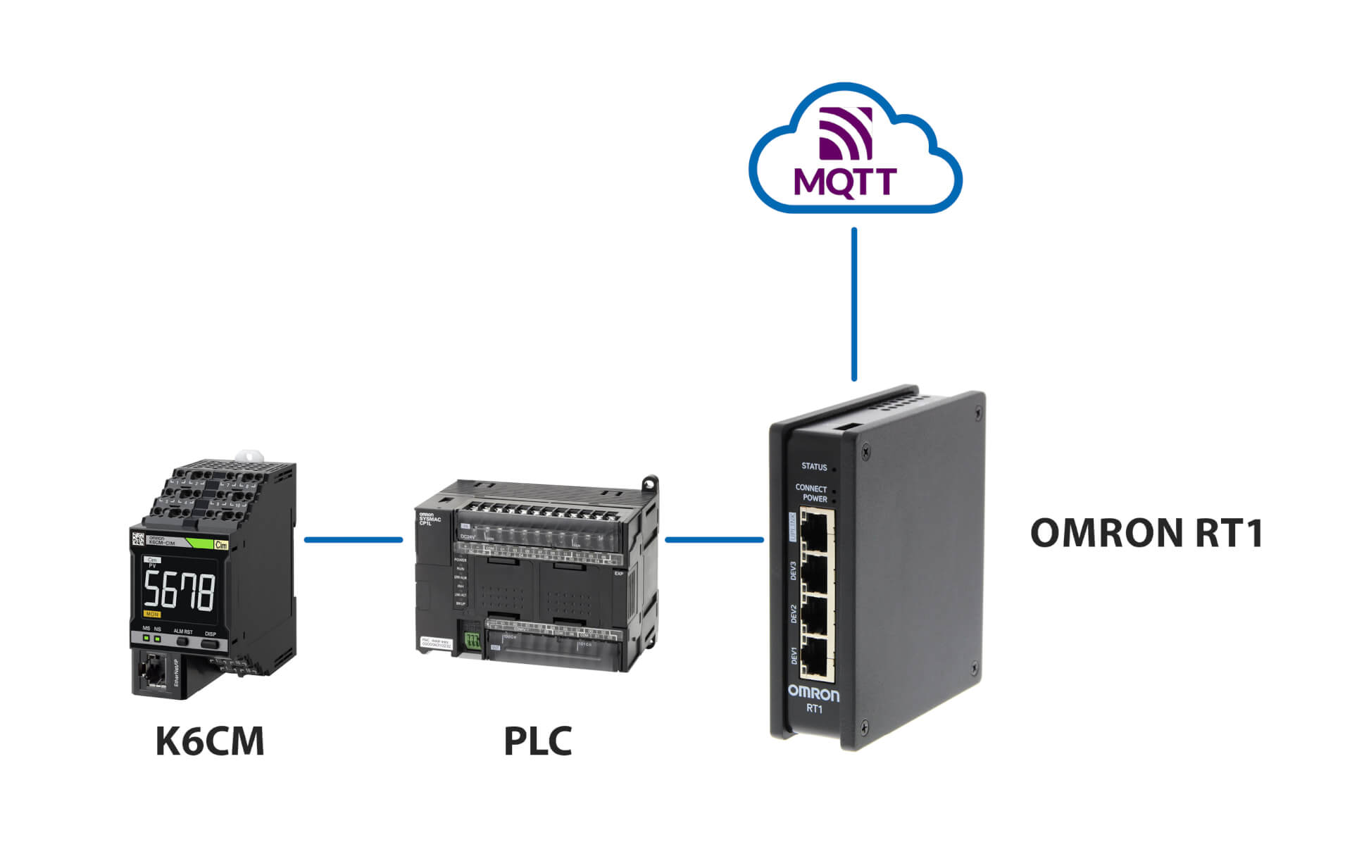
Notifications et surveillance à distance sans API
Avantages de cette solution utilisant OMRON RT1 comme passerelle :
- Notifications par e-mail/SMS en cas d'anomalies détectées par le K6CM
- Connexion sécurisée (gérée par la solution RT1) au Cloud, via une connexion LAN ou 4G
- Connexion sécurisée pour la surveillance à distance et la configuration du K6CM, à l'aide du logiciel de surveillance de condition fourni avec le contrôleur
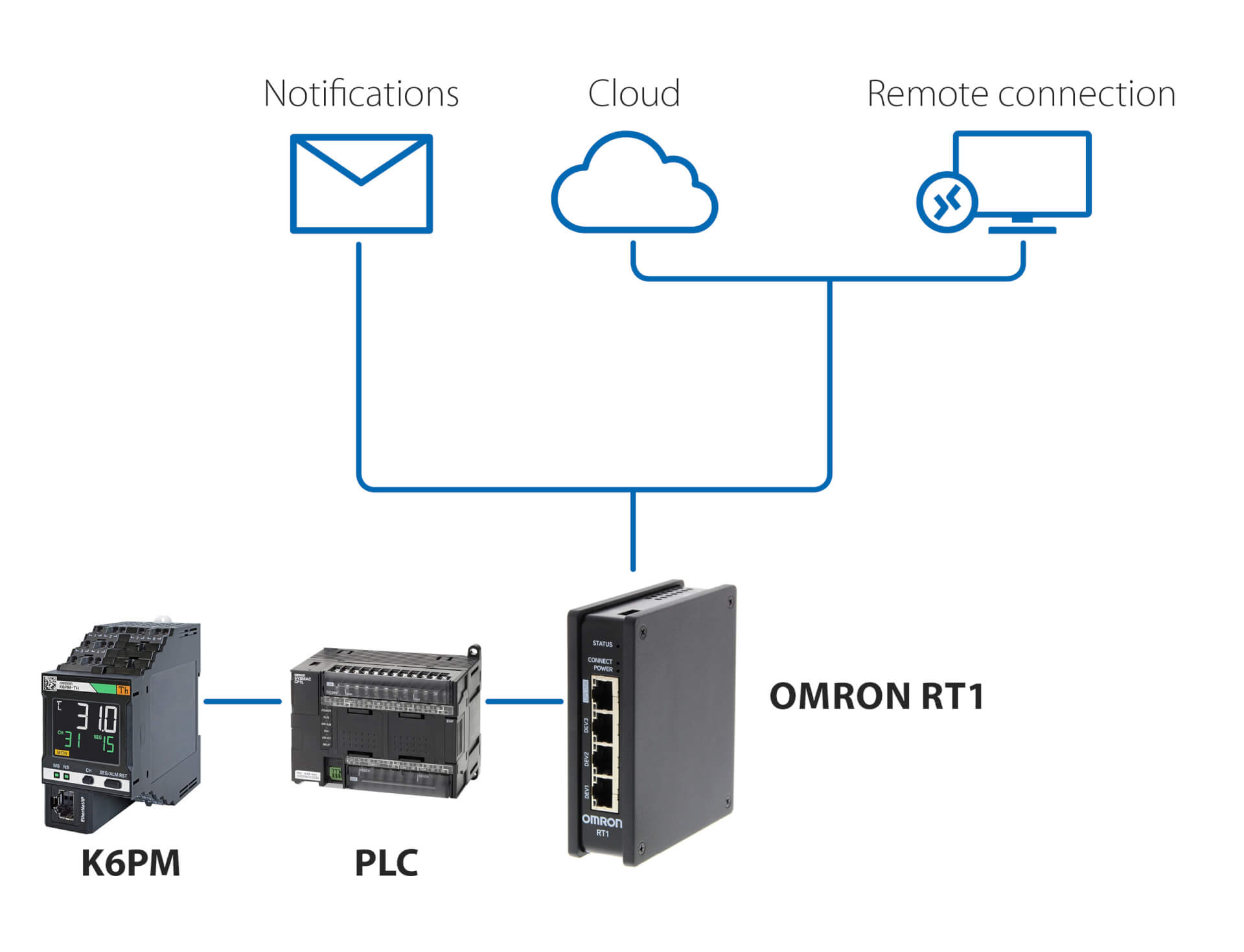
Notifications et surveillance à distance avec API
Avantages de cette solution, utilisant n'importe quelle API et OMRON RT1 comme passerelle :
- Notifications par e-mail/SMS en cas d'anomalies détectées par le K6CM
- Connexion sécurisée (gérée par la solution RT1) au Cloud, via une connexion LAN ou 4G
- Connexion sécurisée pour la surveillance à distance et la configuration du K6CM, à l'aide du logiciel de surveillance de condition fourni avec le contrôleur
Connexion au serveur MQTT
Produits liés
-
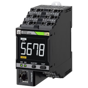
Dispositif de surveillance de l'état du moteur : surveillance du courant
-
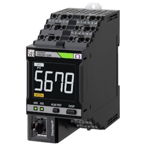
Dispositif de surveillance de l'état du moteur : surveillance de l'isolation
-
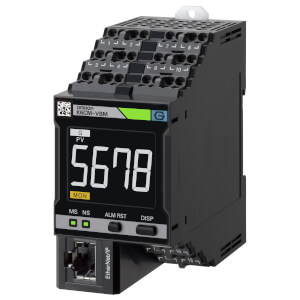
Dispositif de surveillance de l'état du moteur : surveillance des vibrations
-
Dispositif de surveillance de condition : surveillance de l'isolation
Téléchargements